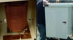
 Left: an isocoil. Right: mounted at WXJC.
LTSpice was just one of many modeling tools
that we used for this. Highly recommended.![]() Click any of these pictures for a larger image.
Click any of these pictures for a larger image.
On This Page:
Back In The Old Days …
SPICE Modeling
If You Need Help
Using LTSpice
My Own Tips
An Active Load
Back In The Old Days …
… when you designed something, you used a slide rule and/or pen and paper to do the math. Then you breadboarded your circuit to confirm that it worked, or used a perfboard and planned on making a lot of changes.
To make the prototype, especially with a tube circuit, you could use a magic box with knobs to select different values of resistors or capacitors. (We called them “decade boxes.”)
Electronic calculators came along and made the math a lot easier. Then came computers in every home and office.
In my never-to-be-humble opinion, anyone who attempts to design a complex circuit the Hard Way(tm) is insane. Use published circuits, tables and other shortcuts to set up your initial design, then use SPICE to fine-tune it.
(Of course, if you’re a manufacturer, you should still do your customers a big favor: test the daylights out of it under every imaginable condition before you offer it to market.)
SPICE Modeling
“SPICE” stands for “Simulation Program (with) Integrated Circuit Emphasis.” It was originally developed in the late 1960’s and early 70’s to help model circuit behavior. Even at that early date, integrated circuits had become too complex for breadboard-and-meter techniques.
The first SPICE tools were text-only and clunky, but that didn’t stop them from becoming extremely popular.
Nowadays, there are commercial SPICE programs available, some of which have very nice point-and-click GUIs and huge libraries of component models. If you already have one, you can use that.
If not, there’s no need to be bland. Linear Technology can SPICE up your life with a free download. Sure, it’s a sales tool; the component libraries focus on their own chips, but LTSpice has more than enough stuff, from resistors to MOSFETs, to build a working “sim” (simulation).
 If you’re a Linux lover, it even
runs fine in Wine. Here ’tis on
my OpenSuSE KDE desktop…
![]()
If You Need Help
(Hmm, that was rather open-ended, wasn’t it?)
The best way to learn how LTSpice works is to play with it. You can’t hurt anything (which is one of the points of computer simulation: no smoke, no fire trucks, no recriminations or insurance claims).
The included help file is uber-geeky, but check that first if you have a question. On the Web, there’s the LTWiki and (of course) you can do a Google search as well.
Google is your friend. Because LTSpice is free, people around the world use it, including many schools. There are zillions of examples online, many written by educators for their own classes.
There’s an LTSpice group at Yahoo that is active, too. They have a nice library of component model files and add ons for LTSpice. They’ll also be glad to answer questions, but respect their time: they’re volunteers. They’ll expect that you’ve already checked the help file and have done a Google or two.
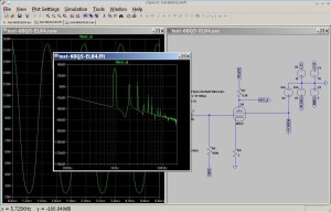 You can even sim tube circuits with
tube models available on the Web.
Here, an FFT of an EL84 sim shows
the harmonics in the output signal.
![]()
Using LTSpice
Google for “LTSpice walkthrough” and you’ll find many on the Web. Simon Bramble in the UK has a good tutorial here. YouTube has some videos, too (this one looks decent).
Basically, SPICE uses a mathematical model for each component in the schematic. These models describe how that part will behave. SPICE then runs your sim in brief steps, noting the changes each time. LTSpice is graphical; it can display waveforms under construction and show changes as the sim is being run.
Obviously, this is going to take a while with a lot of components, with an older computer, or if you’re modeling a non-linear circuit that won’t behave in a fairly straight-line manner.
Because I’m an old Scope Guy (oscilloscope; not the mouthwash), transient analysis feels the best to me. You’ll get a waveform window that acts like a high-powered storage scope. Once you’ve run your sim, you simply click on things in your schematic to see voltage, current, power dissipation and more.
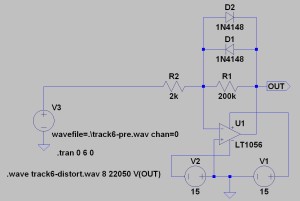 Modeling a distortion box for guitar.
I’m using a .WAV file as input, then
writing a .WAV file as the output.
Yes, I can hear what it sounds like.
![]()
My Own Tips
1. YOU MUST HAVE A GROUND. LTSpice will not simulate a “floating” circuit, or isolated ground(s).
2. If your simulation takes forever to start up and run, it may be too complex. Break it into pieces and run them separately. Check for invalid values on components (common mistake: if you forget the “u” to specify “microfarads” on a capacitor, LTSpice assumes farads).
3. When you’re drawing your schematic, CTRL-R rotates and CTRL-E mirrors (i.e., reverses). Hit the ESC key to end any action while editing. F9 is the “undo” button.
4. The mouse wheel doesn’t scroll the drawing area up and down, it zooms in and out. (Erratically.) Press the SPACE bar to make your schematic fit the screen.
In sum: LTSpice is absolutely amazing. You can design and test a circuit without lifting a solder iron. It’s a great teaching tool as well. I’ll finish with one more example: the active load.
 Hoisting antenna bays for 101.1 FM. The
SPACE bar won’t help here; click to zoom.
![]()
An Active Load
If you Google for “SPICE sim with varying loads,” you’ll probably hit page after page describing how you can use a list of values for a resistor (or some other component). But the active load is a much better way to do it. It acts like a programmed resistance that changes value over time to satisfy the requested current(s).
To use the active load, click the components icon (the “AND” gate symbol on the taskbar), then click on “load” in the list. Place it in your schematic, then right-click to edit. Click “Advanced” and a dialog will appear (see below).
In figure 1, I’ve chosen to do a one-time pulse. Be sure to check the box for, “this is an active load” (I’ve circled it for you). I1 is the starting current; I2 is the ending current; and the Trise(s) is the time to go from I1 to I2. In this example, then the load will assume whatever value of resistance needed to smoothly vary the current from 20mA to 2 amperes over a 1 second interval.
The load obeys Ohm’s law. It will not “create” current (that’s why I say it’s like a programmed resistor). If you only have a 1 volt source with 1K of circuit resistance, you’re not going to get 20mA through the load, much less 2A. The load current will simply go as high as it can and the voltage across the load will drop to a very low value.
But add this fellow to your toolbox. Build some simple sims and play with it. See how it acts. It’s a very useful tool.
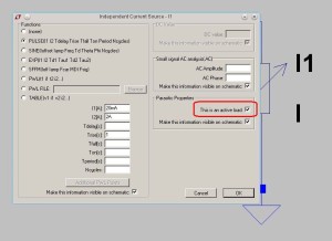 Fig 1: Editing an active load.
![]()
Click here to return to the main page … or just close your browser and start having fun with LTSpice!

